
Note: staff-provided content does not represent an official statement from FARGOS Development, LLC. The policy on staff-authored content can be found here.
Go back to Geoff's home page.
Note: this is one of a set of three related notes on converting Thrustmaster F-22 Pro joysticks, Thrustmaster F-16 TQS and CH Pro Rudder Pedals from obsolete game port interfaces to modern USB-based connectivity. They use an Adafruit ItsyBitsy 32u4 5V board to interface to the existing game controller circuitry and publish the respective state as a USB Human Interface Device.
This set of conversions makes provision for a momentary push button used to trigger a self-calibration cycle. The accompanying software will react to such a button press by flashing the indicator LED rapidly and monitoring the perceived bounds of the various analog inputs. The user should exercise the limits of all of the respective axis associated with the device within the calibration period (typically 15 seconds). The obtained values are saved persistently to the device's EEPROM, thus enabling calibration to survive power cycle events.
The CH Pro Pedals had 3 potentiometers internally and an exposed DPDT switch that allowed the user to select between car and plane mode. In car mode, the pedals were treated as an accelerator and brake pedal pair and the amount of angle pressed on the respective pedal would be indicated. In plane mode, only the third potentiometer would be used to measure the relative skew of the two pedals in their respective channels.
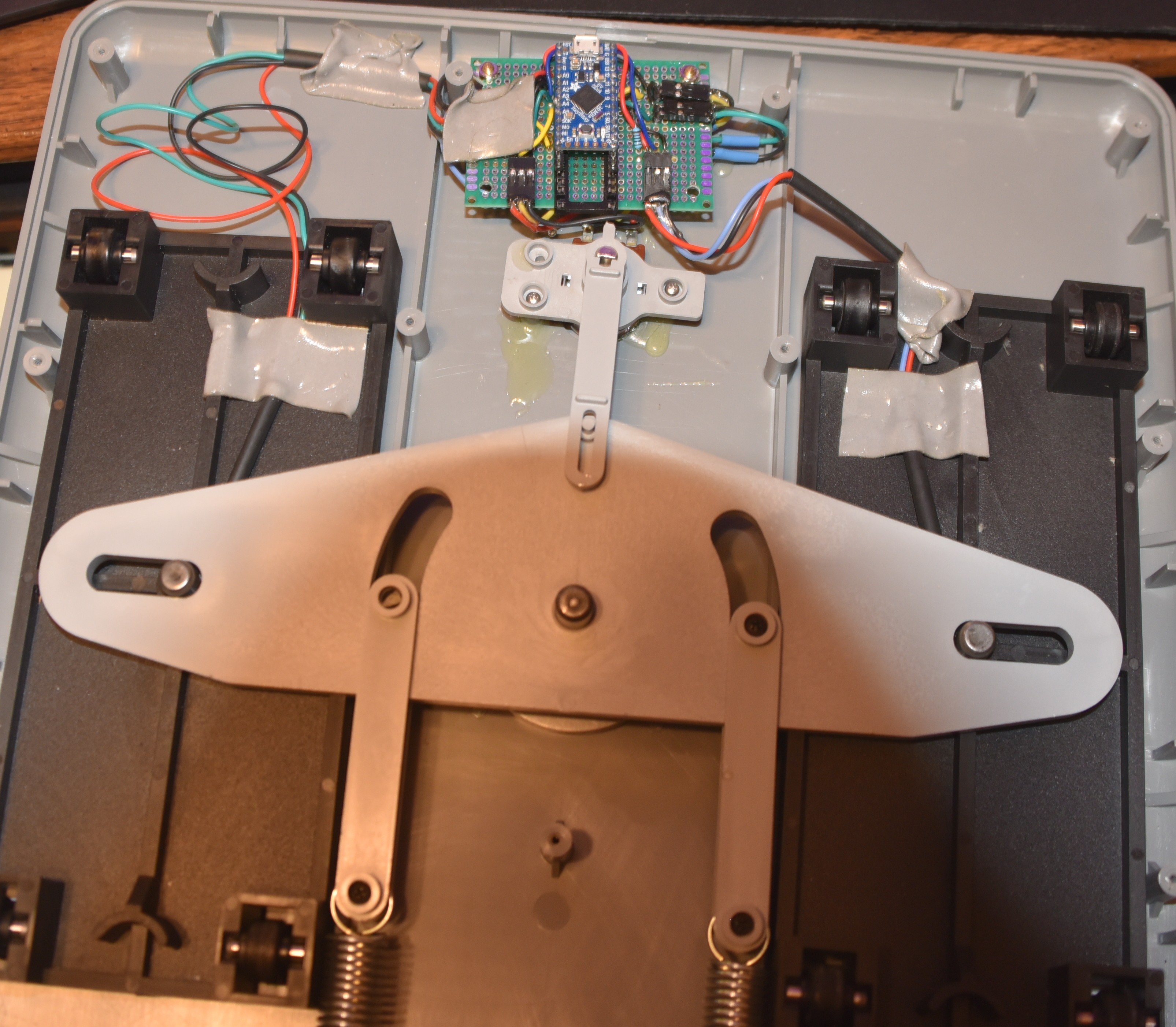
The physical modifications for this particular conversion are more destructive than those of the corresponding alterations made to the Thrustmaster F-22 Pro joystick and F-16 Throttle Quadrant System. The main reason is that the only available gap in the case is that made by the cord removal; the other devices had large openings for the game port plugs that could be reused. A second reason is that the joysticks were wired with just two wires apiece; we want to pass +5 VDC and a ground and read our signal level from the middle terminals. The existing DPDT switch serves to actually change which potentiometers were electically connected whereas we only require an administrative indication of what mode is desired. Consequently, the approach taken here is to unsolder the 6 wires attached to the 3 potentiometers and remove the entire assembly. Further destructive changes can be required: the cord opening in the rear needs to be expanded at least sufficiently allow a USB cable to be plugged in (alternatively, one can be permanently attached and the cable run out through the cord opening). If the self-calibration feature is desired (definitely recommended), holes need to be drilled for the LED and momentary normally-open push button. With the mode selection switch removed, a replacement SPDT switch needs to be put in place and this might require enlargement of the opening, depending on the hardware one has in hand.
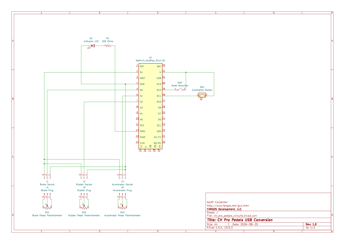
The CH Pro Pedals contains three potentiometers that are used to to measure the relative skew between the pedals in their channels as well as the amount they have been depressed. Note that when the case is upside down, the accelerator pedal will be on the left. Because the original wires are to be unsoldered, one is free to choose whatever color scheme desired for the replacement wires.
| Description | Function | Board Pin |
|---|---|---|
| Accelerator Left | +5 VDC | 5V |
| Accelerator Middle | Accelerator Pedal | A1 |
| Accelerator Right | Ground | GND |
| Rudder Left | +5 VDC | 5V |
| Rudder Middle | Rudder Skew | A2 |
| Rudder Right | Ground | GND |
| Brake Left | +5 VDC | 5V |
| Brake Middle | Brake Pedal | A0 |
| Brake Right | Ground | GND |
Optional self-calibration is supported. A calibration cycle is triggered by depressing a normally open momentary push button switch. Feedback is provided via an indicator LED.
| Function | Board Pin | Notes |
|---|---|---|
| Calibrate | 11 | Other side of switch is connected to ground |
| LED | MOSI | Other side of LED is connected to ground |
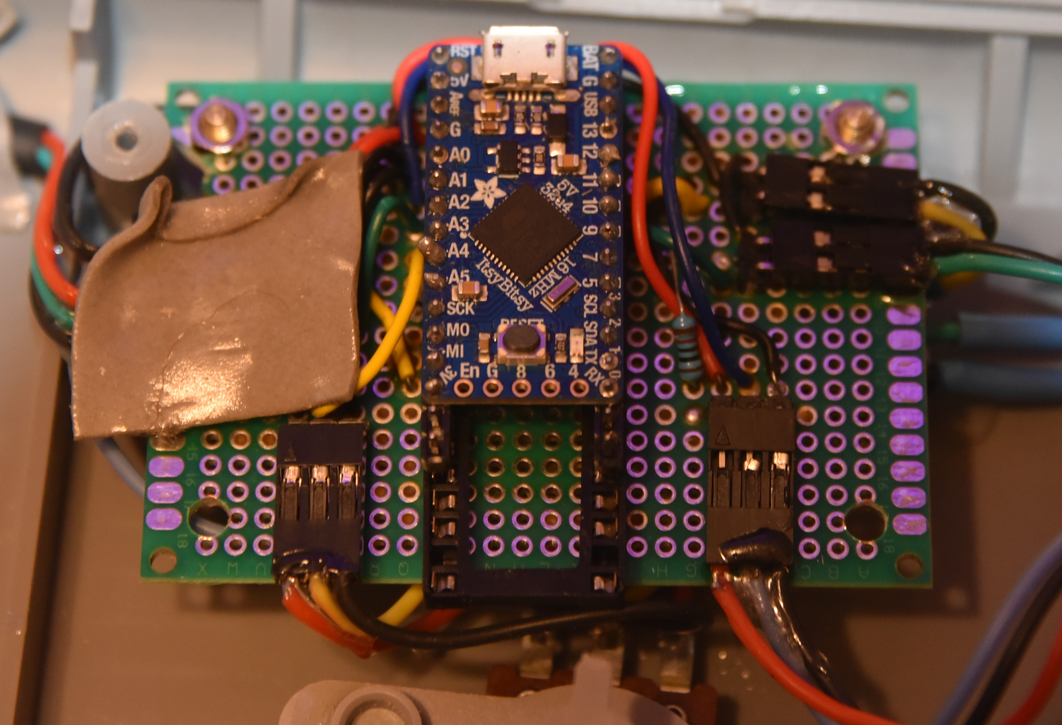
The images shown below illustrate the use of 3-pin JST connectors for the respective potentiometers and 2-pin JST connectors for the mode switch, indicator LED and calibration request push button.
The source code for the CH Pro Pedals interface is illustrated below. The most current release can be retrieved from this CH_Pro_Pedals.ino download link. The .ino files are really C++ source with an alternate file suffix to permit association with the Arduino IDE application.
The comments within the source code provide more detail that will not be repeated here.
For the purposes of programming, the Adafruit ItsyBitsy 32u4 5V is nearly identical to an Arduino Leonardo. Because we want the resulting device to appear correctly named under the Game Controllers control panel, a custom entry is added to the local boards.txt file. It is a duplicate of the leonardo board entry with changes made to the build, build.vid, build.pid and build.usb_product lines. The changes are highlighted below.
itsybitsy_ch.name=CH Rudders atmega32u4
itsybitsy_ch.build.vid=0x2341
itsybitsy_ch.build.pid=0x1024
itsybitsy_ch.build.usb_product="CH Pro Rudder Pedals"
/*! \brief CH Pro Pedals USB conversion using
 * Adafruit ItsyBitsy 32u4 5V.  https://www.adafruit.com/product/3677?
 *
 * \author Geoff Carpenter gcc@fargos.net http://www.fargos.net/gcc.html
 *
 * Requires additions to boards.txt found in:
 * "C:\Users\${USER}\AppData\Local\Arduino15\packages\arduino\hardware\avr\1.8.8\boards.txt"
 * Clone of leonardo board, modified name, build.vid, build.pid and
 * build.usb_product.

itsybitsy_ch.name=CH Rudders atmega32u4
itsybitsy_ch.vid.0=0x2341
itsybitsy_ch.pid.0=0x0036
itsybitsy_ch.vid.1=0x2341
itsybitsy_ch.pid.1=0x8036
itsybitsy_ch.vid.2=0x2A03
itsybitsy_ch.pid.2=0x0036
itsybitsy_ch.vid.3=0x2A03
itsybitsy_ch.pid.3=0x8036
itsybitsy_ch.upload_port.0.vid=0x2341
itsybitsy_ch.upload_port.0.pid=0x0036
itsybitsy_ch.upload_port.1.vid=0x2341
itsybitsy_ch.upload_port.1.pid=0x8036
itsybitsy_ch.upload_port.2.vid=0x2A03
itsybitsy_ch.upload_port.2.pid=0x0036
itsybitsy_ch.upload_port.3.vid=0x2A03
itsybitsy_ch.upload_port.3.pid=0x8036
itsybitsy_ch.upload_port.4.board=leonardo

itsybitsy_ch.upload.tool=avrdude
itsybitsy_ch.upload.tool.default=avrdude
itsybitsy_ch.upload.tool.network=arduino_ota
itsybitsy_ch.upload.protocol=avr109
itsybitsy_ch.upload.maximum_size=28672
itsybitsy_ch.upload.maximum_data_size=2560
itsybitsy_ch.upload.speed=57600
itsybitsy_ch.upload.disable_flushing=true
itsybitsy_ch.upload.use_1200bps_touch=true
itsybitsy_ch.upload.wait_for_upload_port=true

itsybitsy_ch.bootloader.tool=avrdude
itsybitsy_ch.bootloader.tool.default=avrdude
itsybitsy_ch.bootloader.low_fuses=0xff
itsybitsy_ch.bootloader.high_fuses=0xd8
itsybitsy_ch.bootloader.extended_fuses=0xcb
itsybitsy_ch.bootloader.file=caterina/Caterina-Leonardo.hex
itsybitsy_ch.bootloader.unlock_bits=0x3F
itsybitsy_ch.bootloader.lock_bits=0x2F

itsybitsy_ch.build.mcu=atmega32u4
itsybitsy_ch.build.f_cpu=16000000L
itsybitsy_ch.build.vid=0x2341
itsybitsy_ch.build.pid=0x1024
itsybitsy_ch.build.usb_product="CH Pro Rudder Pedals"
itsybitsy_ch.build.board=AVR_LEONARDO
itsybitsy_ch.build.core=arduino
itsybitsy_ch.build.variant=leonardo
itsybitsy_ch.build.extra_flags={build.usb_flags}
 */

/* There are three (3) potentiometers in the CH Pro Pedals board.
 * Depending on the selection of the Car / Plane switch,
 * either the two (2) individual potentiometers in each of the
 * pedals are used to determine brake and accelerator position
 * or the third potentiometer is used by itself to measure
 * relative depth difference between the two pedal slide positions.
 *
 * An external SPDT switch is used to select between the 2 modes
 * and is read at startup.
 */

#define ACCELERATOR_AXIS_PIN A1
#define RUDDER_AXIS_PIN A2
#define BRAKE_AXIS_PIN A0

#define MODE_SELECT_PIN 12

/*! \brief Support internal calibration */
#define SUPPORT_CALIBRATION 1
#if SUPPORT_CALIBRATION
/*! \brief GPIO pin used use for momentary push button to trigger manual calibration.
The button is between ground and this GPIO pin. */
#define CALIBRATE_BUTTON_PIN 11
/*!\brief GPIO pin  used to drive an indicator LED. */
#define INDICATOR_LED MOSI
#endif
/*! \brief Amount of time manual calibration cycle lasts */
#define CALIBRATION_DURATION_MS (15 * 1000)
/*! \brief Sample rate per second. Not guaranteed to be achieved,
 but rate will be no faster. */
#define SAMPLE_RATE_PER_SECOND 100
/*! brief Delay between polling cycles in milliseconds.
  Normally derived from SAMPLE_RATE_PER_SECOND.
 */
#define POLL_DELAY_MS (1000 / (SAMPLE_RATE_PER_SECOND))


/* Unique id for device to be handed to Joystick constructor. */
#define MY_PEDAL_JOYSTICK_ID 6

#define LOG_ENABLED 1
/* These log interfaces are compatible with the advanced thread-safe
 * logging API made available by FARGOS Development, LLC.
 * See http://www.fargos.net/documents/FARGOSutilsLibrary.html
 */
#if LOG_ENABLED > 0
#include <Streaming.h>
#if LOG_ENABLED > 2
#define LOG_COUT(level) Serial << F(__FILE__) << F(":") << __LINE__ << F("\t") << F(#level) << F("\t")
#else
#define LOG_COUT(level) Serial << F(":") << __LINE__ << F("\t") << F(#level) << F("\t")
#endif
#define LOG_ENDLINE endl
#endif

/*! \brief Console baud rate
 *
 * This value should match the baud rate selected in the Arduino IDE's
 * serial monitor window or a dedicated terminal program like Putty.
 */
#define CONSOLE_BAUD_RATE 115200

#include <Joystick.h>
#include <EEPROM.h>


#define MAX_ANALOG_VALUE 1023
#define ANALOG_MIDPOINT (((MAX_ANALOG_VALUE + 1) / 2) - 1)
#define MAX_AXIS_VALUE (((MAX_ANALOG_VALUE + 1) / 2) - 1)
#define MIN_AXIS_VALUE (-MAX_AXIS_VALUE)


static enum PedalModes { NOT_SET,
                         CAR,
                         PLANE } pedalMode;

static uint8_t getPedalMode() {
  return (pedalMode = (pedalMode == NOT_SET) ? (digitalRead(MODE_SELECT_PIN) + 1) : pedalMode);
}

static Joystick_ joystick_object(MY_PEDAL_JOYSTICK_ID,
                                 JOYSTICK_TYPE_JOYSTICK, 0, 0,
                                 false, false, false, false, false, false,
                                 getPedalMode() == PLANE, false,
                                 getPedalMode() == CAR,
                                 getPedalMode() == CAR, false);
static Joystick_ *joystickObj = &joystick_object;

static unsigned long startCalibrateMode_ms;

#define TOTAL_AXES 3
static const uint8_t axisPin[TOTAL_AXES] = { ACCELERATOR_AXIS_PIN, BRAKE_AXIS_PIN, RUDDER_AXIS_PIN };
static const bool invertAxis[TOTAL_AXES] = { true, false, false };

enum eAxisLabel { ACCELERATOR,
                  BRAKE,
                  RUDDER };

struct AxisCalibrationData {
  uint16_t minCalibration;
  uint16_t maxCalibration;
  uint16_t centerCalibration;
};

static AxisCalibrationData calibrationData[TOTAL_AXES] = {
  { 0, MAX_ANALOG_VALUE, (MAX_ANALOG_VALUE + 1) / 2 },
  { 0, MAX_ANALOG_VALUE, (MAX_ANALOG_VALUE + 1) / 2 },
  { 0, MAX_ANALOG_VALUE, (MAX_ANALOG_VALUE + 1) / 2 }
};

static uint8_t indicatorState;
static uint32_t indicatorBlinkCount;
static uint32_t indicatorBlinkRate;
static unsigned long indicatorBlinkUntilMillis;

static const char compiledOnDate[6 + 1] = {
  // YY year
  __DATE__[9], __DATE__[10],

  // First month letter, Oct Nov Dec = '1' otherwise '0'
  (__DATE__[0] == 'O' || __DATE__[0] == 'N' || __DATE__[0] == 'D') ? '1' : '0',

  // Second month letter
  (__DATE__[0] == 'J')   ? ((__DATE__[1] == 'a') ? '1' :  // Jan, Jun or Jul
                            ((__DATE__[2] == 'n') ? '6' : '7'))
  : (__DATE__[0] == 'F') ? '2'
                         :  // Feb
    (__DATE__[0] == 'M') ? (__DATE__[2] == 'r') ? '3' : '5'
                         :  // Mar or May
    (__DATE__[0] == 'A') ? (__DATE__[1] == 'p') ? '4' : '8'
                         :  // Apr or Aug
    (__DATE__[0] == 'S') ? '9'
                         :  // Sep
    (__DATE__[0] == 'O') ? '0'
                         :  // Oct
    (__DATE__[0] == 'N') ? '1'
                         :  // Nov
    (__DATE__[0] == 'D') ? '2'
                         :  // Dec
    0,

  // First day letter, replace space with digit
  __DATE__[4] == ' ' ? '0' : __DATE__[4],

  // Second day letter
  __DATE__[5],

  '\0'
};

static void load_calibration_data(uint8_t axisId) {
  uint8_t *record = reinterpret_cast<uint8_t *>(calibrationData + axisId);
  uint8_t *base = reinterpret_cast<uint8_t *>(calibrationData);
  int offset = record - base;
  EEPROM.get(offset, calibrationData[axisId]);
  if (calibrationData[axisId].minCalibration == ~0) {  // not set in EEPROM, assign default
#if LOG_ENABLED
    LOG_COUT(info) << F("set minCalibration[") << axisId << F("] to 0") << LOG_ENDLINE;
#endif
    calibrationData[axisId].minCalibration = 0;
  }
  if (calibrationData[axisId].maxCalibration == ~0) {  // not set in EEPROM, assign default
#if LOG_ENABLED
    LOG_COUT(info) << F("set maxCalibration[") << axisId << F("] to MAX_ANALOG") << LOG_ENDLINE;
#endif
    calibrationData[axisId].maxCalibration = MAX_ANALOG_VALUE;
  }
  if (calibrationData[axisId].centerCalibration == ~0) {  // not set
#if LOG_ENABLED
    LOG_COUT(info) << F("set centerCalibration[") << axisId << F("] to midpoint") << LOG_ENDLINE;
#endif
    calibrationData[axisId].centerCalibration = (calibrationData[axisId].minCalibration + calibrationData[axisId].maxCalibration) / 2;
  }
#if LOG_ENABLED
  LOG_COUT(info) << F("loaded calibration[") << axisId << F("] min=") << calibrationData[axisId].minCalibration << F(" max=") << calibrationData[axisId].maxCalibration << F(" center=") << calibrationData[axisId].centerCalibration << LOG_ENDLINE;
#endif
}

static void save_calibration_data(uint8_t axisId) {
  uint8_t *record = reinterpret_cast<uint8_t *>(calibrationData + axisId);
  uint8_t *base = reinterpret_cast<uint8_t *>(calibrationData);
  int offset = record - base;
  EEPROM.put(offset, calibrationData[axisId]);
}

uint32_t totalReadCount;

static int32_t read_joystick_pin(uint8_t pin, uint16_t minValue, uint16_t maxValue, uint16_t midpoint, bool invert = false) {
  totalReadCount += 1;
  int16_t value = analogRead(pin);
  if (invert) {
    value = maxValue - value;
    if (value < 0) value = 0;
  }
  if (value < minValue) value = minValue;
  if (value > maxValue) value = maxValue;

  int32_t scaled_result;
  if (value < midpoint) {
    int32_t range = (midpoint - minValue) + 1;
    int32_t offset = midpoint - value;
    if (offset >= range) offset = range - 1;
    scaled_result = (offset * ANALOG_MIDPOINT) / range;
    scaled_result = ANALOG_MIDPOINT - scaled_result;
    if (scaled_result < 0) scaled_result = 0;
  } else {
    int32_t range = (maxValue - midpoint) + 1;
    int32_t offset = value - midpoint;
    if (offset >= range) offset = range - 1;
    scaled_result = (offset * ANALOG_MIDPOINT) / range;
    scaled_result += ANALOG_MIDPOINT;
    if (scaled_result > MAX_ANALOG_VALUE) scaled_result = MAX_ANALOG_VALUE;
  }
  int32_t result = (scaled_result * (MAX_ANALOG_VALUE + 1)) / ((MAX_AXIS_VALUE - MIN_AXIS_VALUE) + 1);

#if LOG_ENABLED > 3
  LOG_COUT(info) << F("pin=") << pin << F(" val=") << value << F(" minVal=") << minValue << F(" maxVal=") << maxValue << F(" midPoint=") << midpoint << F(" scaled_result=") << scaled_result << LOG_ENDLINE;
#endif
  return (result);
}


static void read_joystick_state() {
  uint8_t startAxis = (pedalMode == CAR) ? ACCELERATOR : RUDDER;
  uint8_t lastAxis = (pedalMode == CAR) ? BRAKE : RUDDER;
  for (uint8_t i = startAxis; i <= lastAxis; i += 1) {
    if (pedalMode == CAR) {  // have to read more than one analog pin
      int32_t discardValue = read_joystick_pin(axisPin[i], calibrationData[i].minCalibration,
                                               calibrationData[i].maxCalibration, calibrationData[i].centerCalibration, invertAxis[i]);
    }
    int32_t reading = read_joystick_pin(axisPin[i], calibrationData[i].minCalibration,
                                        calibrationData[i].maxCalibration, calibrationData[i].centerCalibration, invertAxis[i]);
    int32_t scaled_value = (pedalMode == CAR) ? reading : reading + MIN_AXIS_VALUE;
#if LOG_ENABLED > 1
    LOG_COUT(info) << F("axis=") << i << F(" pin=") << axisPin[i] << F(" reading=") << reading << F(" scaled=") << scaled_value << LOG_ENDLINE;
#endif
    switch (i) {
      case ACCELERATOR:
        joystickObj->setAccelerator(scaled_value);
        break;
      case BRAKE:
        joystickObj->setBrake(scaled_value);
        break;
      case RUDDER:
        joystickObj->setRudder(scaled_value);
        break;
      default:
#if LOG_ENABLED
        LOG_COUT(info) << F("no support") << LOG_ENDLINE;
#endif
        break;
    }  // end switch
  }    // end for
}

#if SUPPORT_CALIBRATION
static void monitorCalibration() {
  uint8_t startAxis = (pedalMode == CAR) ? ACCELERATOR : RUDDER;
  uint8_t lastAxis = (pedalMode == CAR) ? BRAKE : RUDDER;
  for (uint8_t i = startAxis; i <= lastAxis; i += 1) {
    uint8_t pin = axisPin[i];
    uint16_t value = analogRead(pin);
    if (value > calibrationData[i].maxCalibration) calibrationData[i].maxCalibration = value;
    if (value < calibrationData[i].minCalibration) calibrationData[i].minCalibration = value;
  }
}

static bool checkForCalibration() {
  if (startCalibrateMode_ms == 0) {
    uint8_t val = digitalRead(CALIBRATE_BUTTON_PIN);
    if (val == HIGH) {
      return (false);
    }
#if LOG_ENABLED
    LOG_COUT(info) << F("start calibration") << LOG_ENDLINE;
#endif
    startCalibrateMode_ms = millis();
    indicatorState = HIGH;
    digitalWrite(INDICATOR_LED, HIGH);
    indicatorBlinkRate = 10;
    // we assume rudder pedals are centered at time of initial button press,
    // take several samples and average for calculation of center
    uint8_t startAxis = (pedalMode == CAR) ? ACCELERATOR : RUDDER;
    uint8_t lastAxis = (pedalMode == CAR) ? BRAKE : RUDDER;
    for (uint8_t i = startAxis; i <= lastAxis; i += 1) {
      uint8_t pin = axisPin[i];
      if (i == RUDDER) {  // rudder potentiometer
        int32_t aveValue = 0;
        enum { SAMPLE_COUNT = 5 };
        for (uint8_t count = 0; count < SAMPLE_COUNT; count += 1) {
          int32_t center_value = read_joystick_pin(axisPin[i], calibrationData[i].minCalibration,
                                                   calibrationData[i].maxCalibration, calibrationData[i].centerCalibration,
                                                   invertAxis[i]);
          aveValue += center_value;
        }
        calibrationData[i].centerCalibration = aveValue / SAMPLE_COUNT;
#if LOG_ENABLED
        LOG_COUT(info) << F("set center ") << i << F(" to ") << calibrationData[i].centerCalibration << LOG_ENDLINE;
#endif
        calibrationData[i].minCalibration = calibrationData[i].centerCalibration;
        calibrationData[i].maxCalibration = calibrationData[i].centerCalibration;
      } else {
        calibrationData[i].minCalibration = MAX_ANALOG_VALUE;
        calibrationData[i].maxCalibration = 0;
      }
    }
  }
  // in calibration mode
  monitorCalibration();
  unsigned long now = millis();
  if (now > (startCalibrateMode_ms + CALIBRATION_DURATION_MS)) {
#if LOG_ENABLED
    LOG_COUT(info) << F("calibration ends") << LOG_ENDLINE;
#endif
    if (pedalMode == CAR) {
      for (uint8_t i = ACCELERATOR; i <= BRAKE; i += 1) {
        calibrationData[i].centerCalibration = (calibrationData[i].minCalibration + calibrationData[i].maxCalibration) / 2;
        save_calibration_data(i);
      }
    } else {  // in PLANE mode
      save_calibration_data(RUDDER);
    }
    startCalibrateMode_ms = 0;  // turn off
    indicatorState = LOW;
    indicatorBlinkRate = 0;
    digitalWrite(INDICATOR_LED, LOW);
  }
}
#endif /* SUPPORT_CALIBRATION */

void setup() {
  delay(500);  // stabilize after power-on
#if LOG_ENABLED
  // Setup hardware serial port
  Serial.begin(CONSOLE_BAUD_RATE);

  unsigned long start = millis();
  while (!Serial) {
    unsigned long delayed = millis() - start;
    if (delayed > 5000) break;
  }
  LOG_COUT(info) << F("CH Pro Pedals firmware compiled on date ") << compiledOnDate << LOG_ENDLINE;
  LOG_COUT(info) << F("Original from Geoff Carpenter gcc@fargos.net http://www.fargos.net/gcc.html") << LOG_ENDLINE;
  LOG_COUT(Info) << F("poll delay=") << POLL_DELAY_MS << LOG_ENDLINE;
#endif

  pinMode(MODE_SELECT_PIN, INPUT_PULLUP);
  pinMode(ACCELERATOR_AXIS_PIN, INPUT);
  pinMode(BRAKE_AXIS_PIN, INPUT);
  pinMode(RUDDER_AXIS_PIN, INPUT);

  pinMode(LED_BUILTIN, OUTPUT);
#if SUPPORT_CALIBRATION
  pinMode(CALIBRATE_BUTTON_PIN, INPUT_PULLUP);
  pinMode(INDICATOR_LED, OUTPUT);
  digitalWrite(INDICATOR_LED, LOW);
  indicatorBlinkRate = 100;
  indicatorBlinkUntilMillis = millis() + 10000;
  for (uint8_t i = 0; i < TOTAL_AXES; i += 1) {
    load_calibration_data(i);
  }
#endif

  joystickObj->begin(false);  // Set auto-send to false for better performance
  if (pedalMode != CAR) {
#if LOG_ENABLED
    LOG_COUT(info) << F("active mode = PLANE") << LOG_ENDLINE;
#endif
    joystickObj->setRudderRange(MIN_AXIS_VALUE, MAX_AXIS_VALUE);
  } else {
#if LOG_ENABLED
    LOG_COUT(info) << F("active mode = CAR") << LOG_ENDLINE;
#endif
    joystickObj->setBrakeRange(0, MAX_ANALOG_VALUE);
    joystickObj->setAcceleratorRange(0, MAX_ANALOG_VALUE);
  }
}

static bool blinkLED(unsigned long currentTime) {
  static uint32_t count;
  static uint8_t ledState;

  count += 1;
  if (count < 100) return (false);
  // toggle LED state
  count = 0;
  ledState = 1 - ledState;
  digitalWrite(LED_BUILTIN, ledState);
  //    digitalWrite(LATCH_PIN, ledState);

  return (true);
}

#if SUPPORT_CALIBRATION
static bool blinkIndicatorLED(unsigned long currentTime) {
  bool changed = false;
  if (indicatorBlinkUntilMillis != 0) {
    if (indicatorBlinkUntilMillis <= currentTime) {  // reached end of cycle
      changed = indicatorState;
      indicatorBlinkUntilMillis = 0;  // turn off
      indicatorBlinkRate = 0;
      indicatorState = LOW;
      digitalWrite(INDICATOR_LED, LOW);
    }
  }
  if (indicatorBlinkRate != 0) {
    indicatorBlinkCount += 1;
    //    LOG_COUT(info) << F("count=") << indicatorBlinkCount << F(" rate=") << indicatorBlinkRate << LOG_ENDLINE;
    if (indicatorBlinkCount >= indicatorBlinkRate) {
      //      LOG_COUT(info) << F("Blink indicator") << LOG_ENDLINE;
      indicatorBlinkCount = 0;
      indicatorState = 1 - indicatorState;
      digitalWrite(INDICATOR_LED, indicatorState);
      changed = true;
    }
  }
  return (changed);
}
#endif

static unsigned long delayIfNeeded(unsigned long now) {
  static unsigned long lastTime;

  unsigned long nextTime = lastTime + POLL_DELAY_MS;
  if (now < nextTime) {
#if LOG_ENABLED > 1
//    LOG_COUT(info) << F("delay ms=") << nextTime - now << LOG_ENDLINE;
#endif
    delay(nextTime - now);
    now = millis();
  } else {
#if LOG_ENABLED > 2
    LOG_COUT(info) << F("past delay=") << now - nextTime << LOG_ENDLINE;
#endif
  }
  lastTime = now;
  return (now);
}

void loop() {
  unsigned long now = delayIfNeeded(millis());
  //unsigned long doneTime = millis();
  //LOG_COUT(info) << F("duration0=") << doneTime - now << LOG_ENDLINE;
  blinkLED(now);
#if SUPPORT_CALIBRATION
  blinkIndicatorLED(now);
  checkForCalibration();
#endif
  read_joystick_state();
  // Send the updated states to the PC all at
  //unsigned long before = millis();
  joystickObj->sendState();
  //doneTime = millis();
  //LOG_COUT(info) << F("duration4=") << doneTime - now << F(" send=") << doneTime - before << LOG_ENDLINE;
}
/* vim: set expandtab shiftwidth=4 tabstop=4: */

Last Modified: August 27, 2024